
Vt Commodore Ignition Wiring Diagram, Complete Wiring Diagrams For Holden Commodore VT, VX, VY, VZ, VE, VF, 5.36 MB, 03:54, 32,796, John Amahle, 2018-08-01T19:37:41.000000Z, 19, Vt Commodore Ignition Wiring Diagram, to-ja-to-ty-to-my-to-nasz-swiat.blogspot.com, 1272 x 1800, jpeg, bcm pcm 12j swiat nasz, 20, vt-commodore-ignition-wiring-diagram, Anime Arts
Gas tank sending unit wiring diagram help 1. With key on, bridge or connect center wire on tank (usually pink) to the tank ground wire. If the tank has a spade connector, make sure its clean and tight. If gage pegs to full, problem is in the sender in the tank (most likely)
Sunpro tach chanish [zv_1017] chevy fuel sending unit wiring diagram as well boat fuel impa. sulf. isra. mohammedshrine. org I would bet the sending unit is bad but lets check it, a good test i use is that i have a used sending unit i connect to wiring to test the gauge and wiring, if the gauge moves when i move the testing unit then i know the gauge is good and the wiring to, locte the connector at fuel tank, and unplug it, this will be the one the leads to top of the tank and the connector will be on the side be. Most times, the wiring is bad. Use this video as a reference. heres a link to. The fuel gage circuit consists of the sending unit in the fuel tank, the gauge in the dash, and the wiring and dash wiring (or circuit board) between them. As with most sensors, the tank sending unit is simply a variable resistor. Its function is to resist the flow of current from the ground to the gauge depending on the position of the float. Fuel tank sending unit wiring diagram from logicdiagram. b2bnetwork. it to properly read a electrical wiring diagram, one has to find out how the particular components inside the system operate. For example , if a module will be powered up also it sends out a new signal of half the voltage plus the technician does not know this, he would think he provides a problem, as he.
How to wire up a fuel sending unit?

Gm Fuel Sending Unit Wiring Diagram | Cadician's Blog
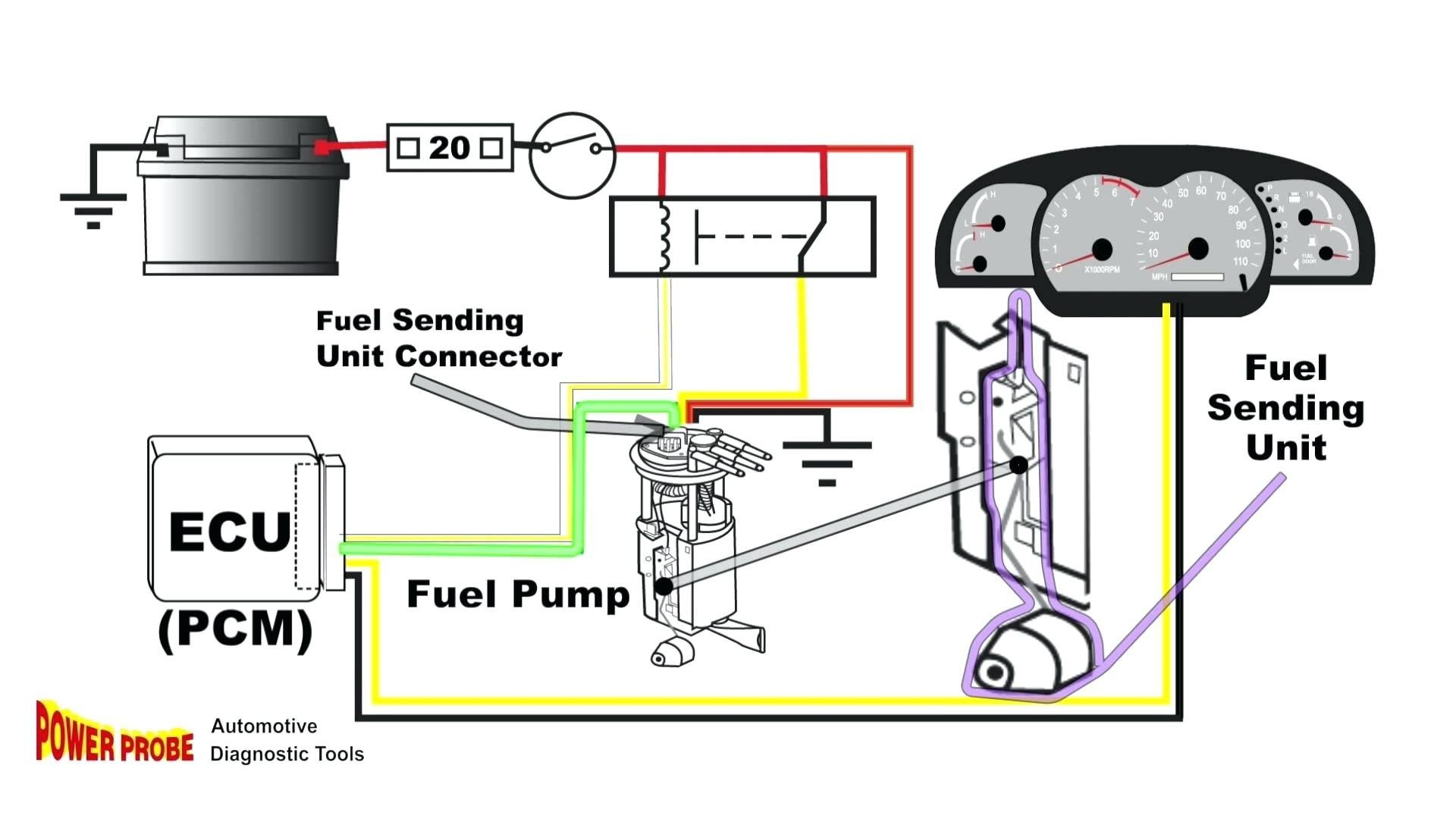
Gm Fuel Sending Unit Wiring Diagram | Cadician's Blog
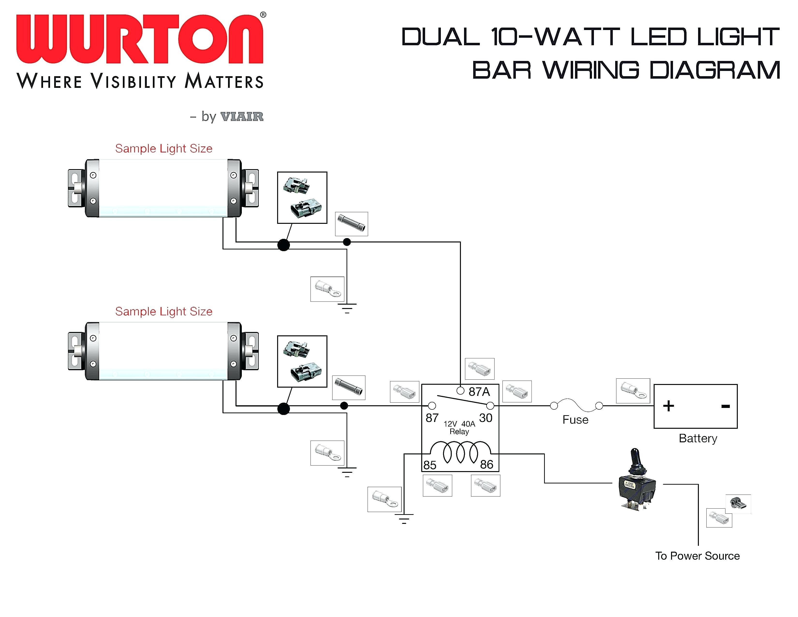
Rci Fuel Cell Sending Unit Wiring Diagram
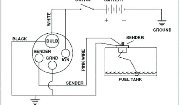
Fuel Gauge Sending Unit Wiring Diagram | Free Wiring Diagram

1973-1977 Monte Carlo Fuel Tank Sending Unit 5/16" Line (2 Outlet - Fuel Sending Unit Wiring
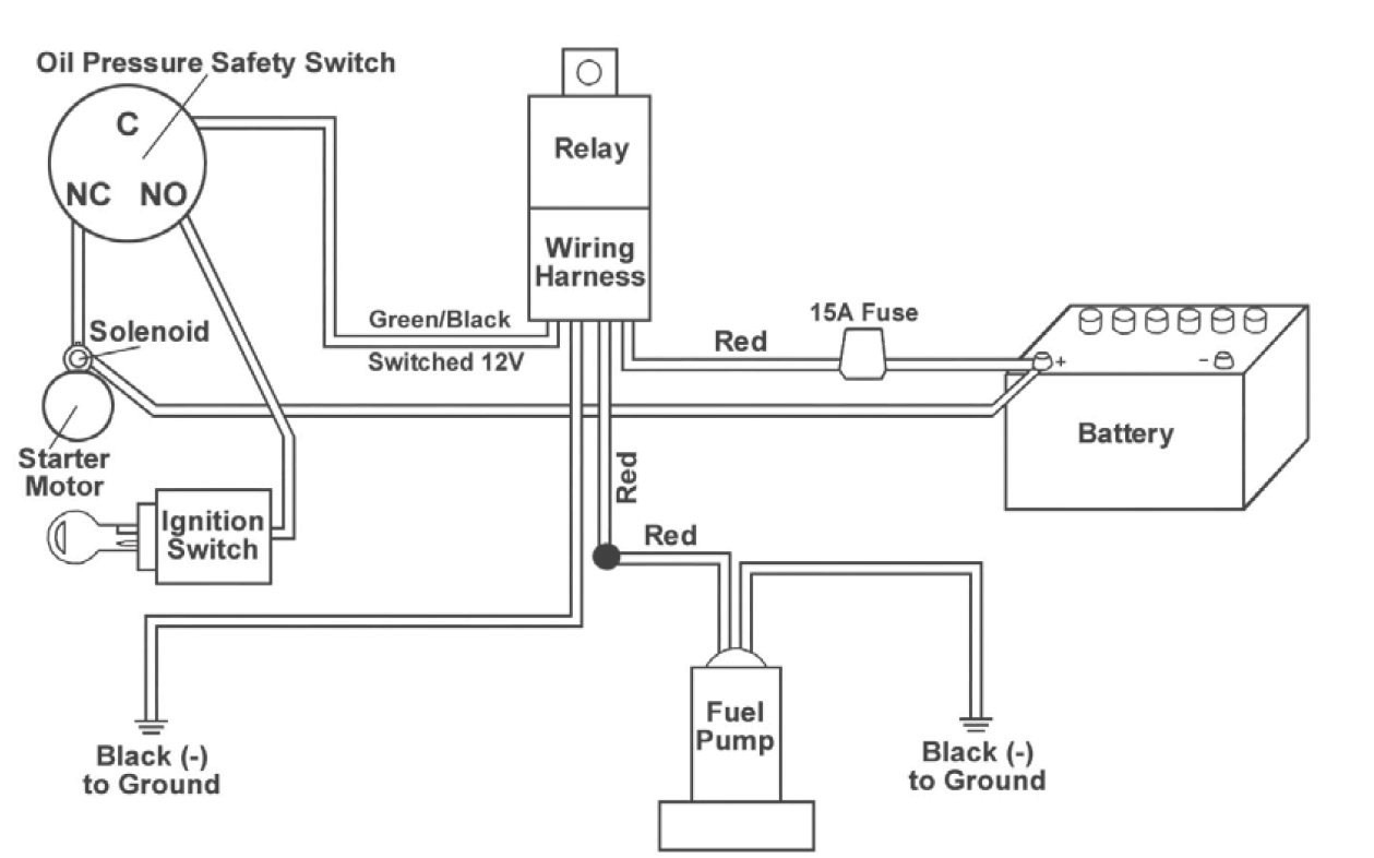
Fuel sending unit wiring | Mustang Forums at StangNet
2G - Which wire to power to fuel level sending unit? | DSMtuners
Rci Fuel Cell Sending Unit Wiring Diagram
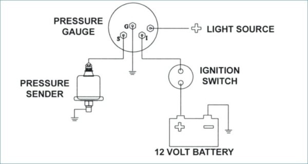
Fuel Gauge Sending Unit Wiring Diagram | Free Wiring Diagram

