Vt Commodore Ignition Wiring Diagram, Complete Wiring Diagrams For Holden Commodore VT, VX, VY, VZ, VE, VF, 5.36 MB, 03:54, 32,796, John Amahle, 2018-08-01T19:37:41.000000Z, 19, Vt Commodore Ignition Wiring Diagram, to-ja-to-ty-to-my-to-nasz-swiat.blogspot.com, 1272 x 1800, jpeg, bcm pcm 12j swiat nasz, 20, vt-commodore-ignition-wiring-diagram, Anime Arts
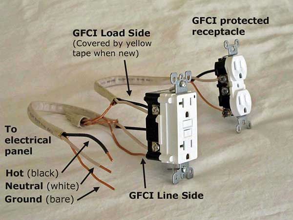
Refer to these diagram about wiring gfci receptacles: Gfci protection is provided at the gfci outlet and to other ordinary outlets. Terminate the black line side wire (the black wire with the yellow wire nut) on the brass line side screw. Terminate the white line side wire (the white wire with the yellow wire nut) on the silver line side screw.
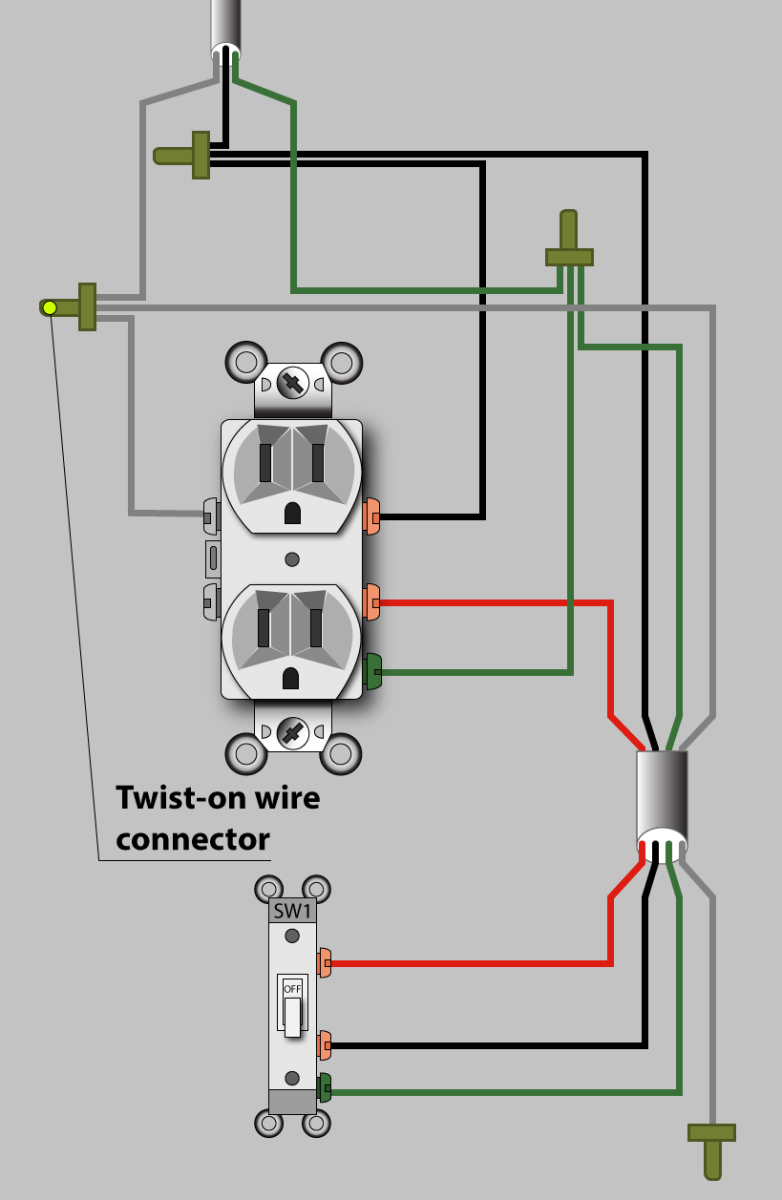
The lower four terminals and ground wire of rcbo has been connected to the spa control box by the following sequence. Gfci diagram wiring receptacle receptacles breaker neutral 120v split wires install wire common using circuit outlets electrical side shared use. Gfci wiring outlet diagram outlets switch wired wire non receptacle wires electrical single side connect configuration pigtail. Wiring residential switch switches 101 way light wire plan four change fixture cable duplex receptacle google. Wiring a split, switched receptacle. — az diy guy www. azdiyguy. com. Wiring switched receptacle split wire wires outlet plug ground cable basic electrical half diy az guy. Wiring diagram 3 way switch split receptacle database How to wire a split receptacle we have 9 pictures about how to wire a split receptacle like wiring diagrams for ground fault circuit interrupter receptacles | gfci, i have a gfci outlet in my kitchen that will not reset.
Gfci Split Receptacle Wiring Diagram - Wiring Diagram

Electrical Outlet Split Circuit Wiring Top Latest Multiple Gfci Outlet Wiring Diagram Diagrams

Gfci Split Receptacle Wiring Diagram Perfect Gfci Split Receptacle Wiring Diagram Switched
Wiring A Split Switched Outlet Cleaver Gfci Split Receptacle Wiring Diagram Switched Outlet Wire
Can You Split A Gfci Receptacle

15 Top Gfci Split Receptacle Wiring Diagram Images - Tone Tastic
Electrical Outlet Split Circuit Wiring Nice Wiring Diagram, Electrical Outlet Save Gfci Split

electrical - Can I wire additional circuits off of GFCI this way? - Home Improvement Stack Exchange

Multiple Gfci Outlet Wiring Diagram / Wiring Diagram Outlets Awesome Wiring A Multiple Outlets
46 Gfci Branch Circuit Wiring Diagram - Wiring Diagram Harness Info

