Vt Commodore Ignition Wiring Diagram, Complete Wiring Diagrams For Holden Commodore VT, VX, VY, VZ, VE, VF, 5.36 MB, 03:54, 32,796, John Amahle, 2018-08-01T19:37:41.000000Z, 19, Vt Commodore Ignition Wiring Diagram, to-ja-to-ty-to-my-to-nasz-swiat.blogspot.com, 1272 x 1800, jpeg, bcm pcm 12j swiat nasz, 20, vt-commodore-ignition-wiring-diagram, Anime Arts
For instance , if a module is usually powered up and it sends out a new signal of half the voltage and the technician will not know this, he would think he has a challenge, as he would. Have you ever had a relay come on and drain your battery while driving? Ever had a relay fail on you when you are far from home? Looking at the diagram, you have terminals 2,3,6,&10.
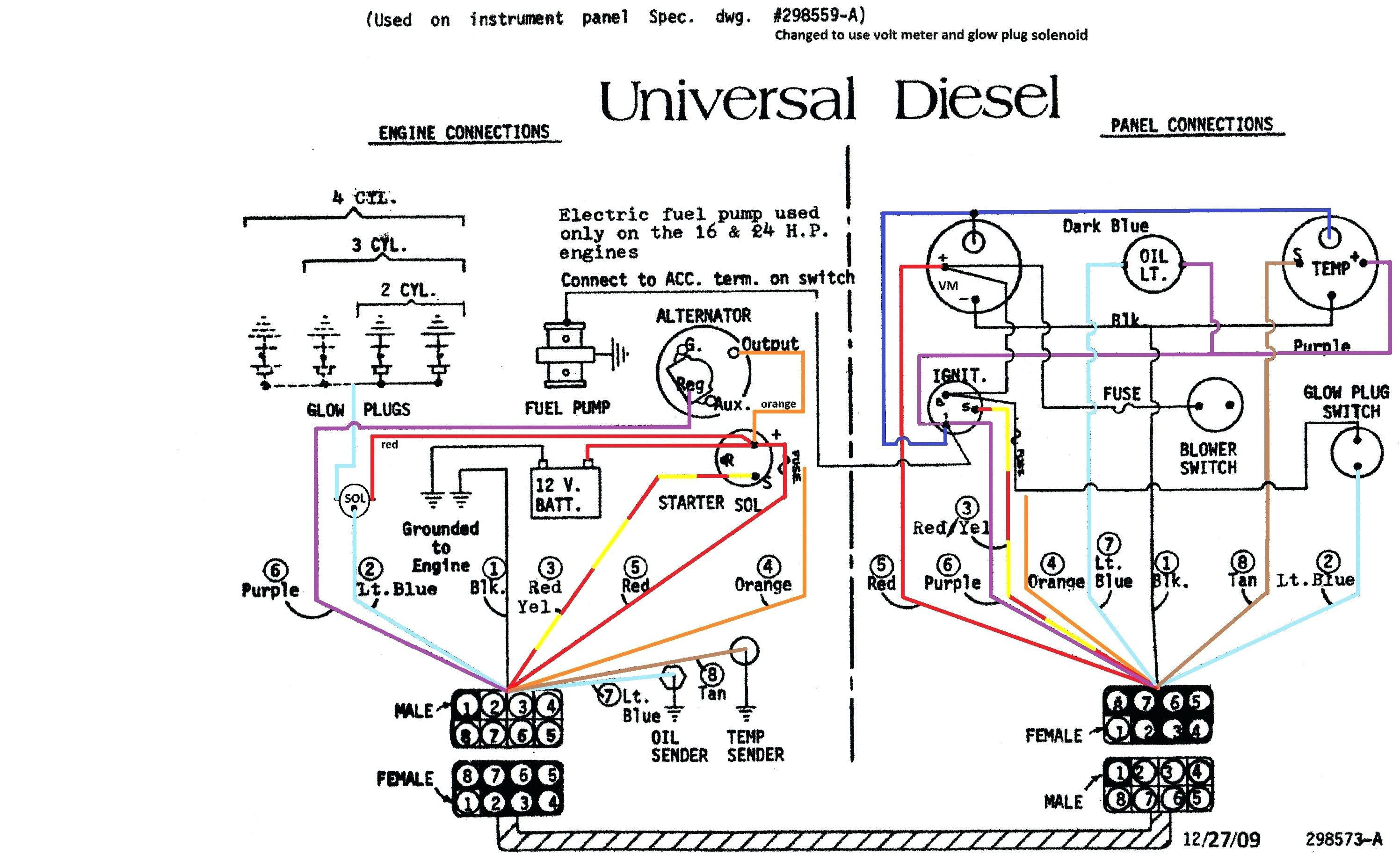
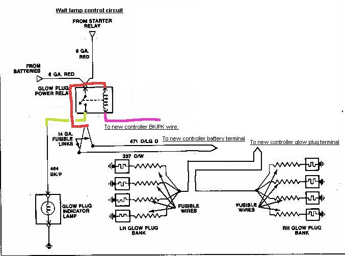
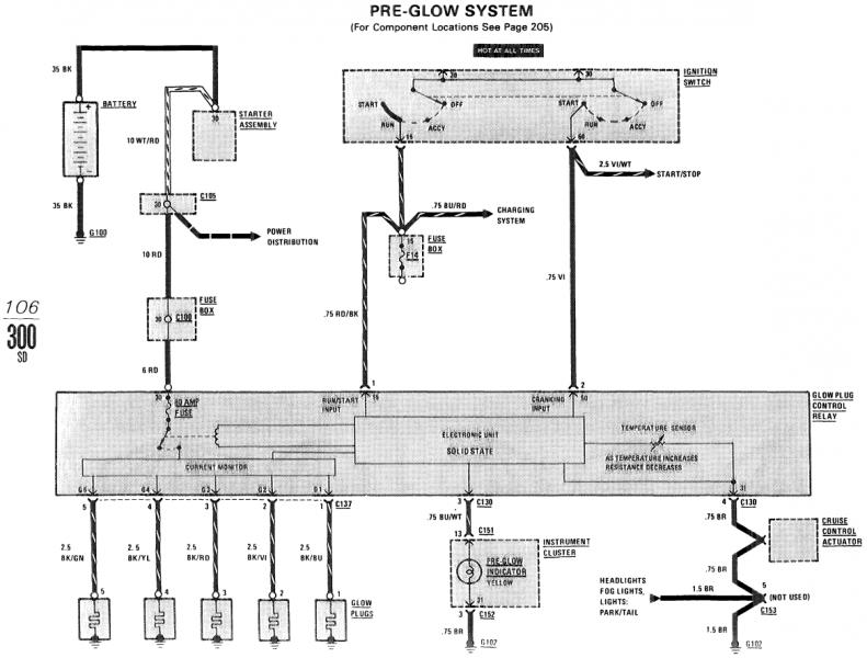
3 is the ground wire controlled by the pcm. 6 is to the glowplugs. 10 is power from the ignition switch. When you turn the key to 'on' there is 12v to 10 constant. The pcm determines if the glowplugs should be activated and for how long. Here are a number of highest rated glow plug relay wiring diagram pictures on internet. Glow plug relay wiring diagram below is a 7. 3 powerstroke glow plug relay wiring diagram. According to earlier, the lines in a kubota glow plug wiring diagram signifies wires. 73l wiring schematic printable very handy.
Glow Plug Timer Circuit - Circuit Diagram Images

7.3 Powerstroke Glow Plug Relay Wiring Diagram - Wiring Diagram

Glow Plug Timer Relay Wiring Diagram - SCRAPBOOKMAMAW

1995 F350 7 3 Glow Plug Relay Wiring Diagram - Wiring Diagram Schema

7.3 Powerstroke Glow Plug Relay Wiring Diagram - Wiring Diagram

Glow Plug Timer Relay Wiring Diagram - 14

Insider: Glow Plug Timer Circuit
7.3 Glow Plug Relay Wiring Diagram

7.3 Powerstroke Glow Plug Relay Wiring Diagram - Cadician's Blog

Glow Plug Timer Relay Wiring Diagram - SCRAPBOOKMAMAW

