Vt Commodore Ignition Wiring Diagram, Complete Wiring Diagrams For Holden Commodore VT, VX, VY, VZ, VE, VF, 5.36 MB, 03:54, 32,796, John Amahle, 2018-08-01T19:37:41.000000Z, 19, Vt Commodore Ignition Wiring Diagram, to-ja-to-ty-to-my-to-nasz-swiat.blogspot.com, 1272 x 1800, jpeg, bcm pcm 12j swiat nasz, 20, vt-commodore-ignition-wiring-diagram, Anime Arts
Slits before the installation and wiring work in order to block foreign objects su ch as cutting and wiring debris. However, when the installation work is completed, make sure to remove the sheet to provide adequate ventilation. Failure to do so may cause fire, equipment failures or malfunctions. Install the product on a flat surface.
· can be connected to the back of a basic unit or expansion unit. · convenient for expanding input/output, receiving power supply from a basic unit or expansion unit. Overseas oriented products meet all kinds of international standards. Use terminal module to replace connector connection or relay terminal row connection, so as to save the wiring inside the cabinet. Plc, fx2n modular extension unit; Make sure to cut off all phases of the power supply externally before attempting installation or wiring work. Failure to do so may cause electric shock or. Dc input (drain / source). In order to extend the input output of the device.
FX5-16EX/ES 仕様 MELSEC iQ-F シーケンサ MELSEC 仕様から探す|三菱電機 FA
Mitsubishi Plc Fx5-16ex/es - Buy Mitsubishi Plc Fx5-16ex/es Product on Alibaba.com
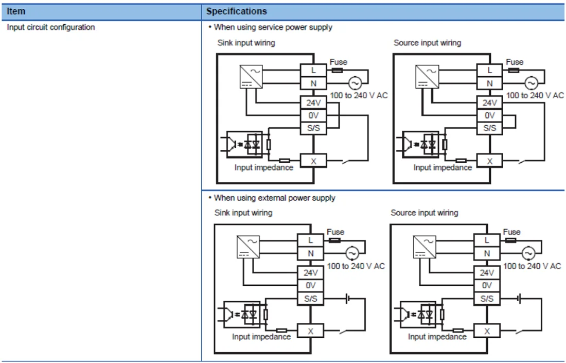
取寄 三菱電機 FX5-16EX/ES I/Oユニット 入力ユニット (DC入力(シンク/ ソース)) (入力 16点) NN :fx5-16ex-es:ANGEL HAM SHOP
Mitsubishi Plc Fx5-16ex/es - Buy Mitsubishi Plc Fx5-16ex/es Product on Alibaba.com
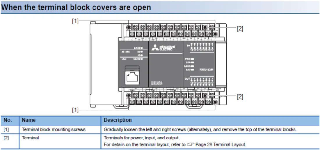
Mở rộng PLC FX5U | MODULE FX5-16EX/ES| MỞ RỘNG PLC FX5-8EX/ES – PLCSAIGON
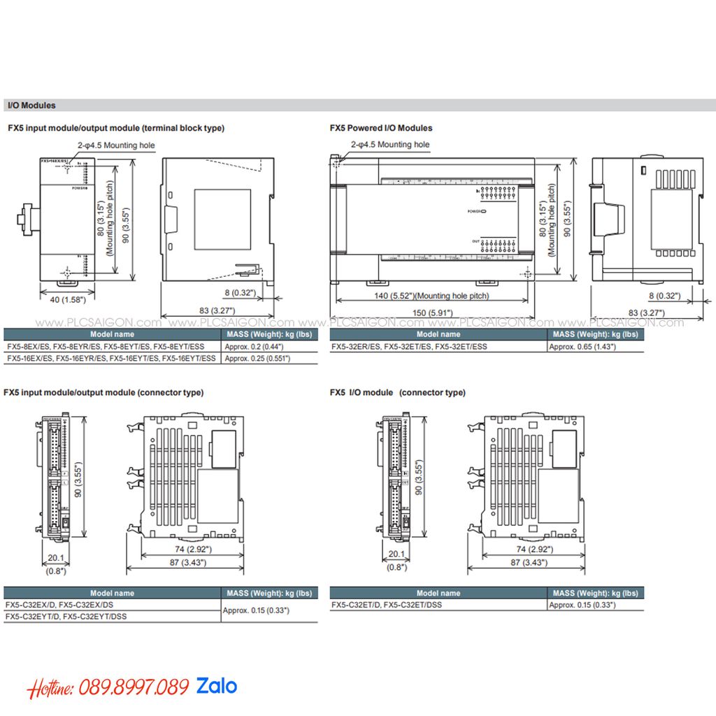
Mitsubishi Plc Fx5-16ex/es - Buy Mitsubishi Plc Fx5-16ex/es Product on Alibaba.com
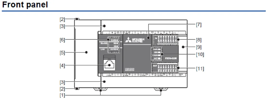
三菱FX5UC与终端模块的输入输出接线图 - 三菱工控自动化产品网:三菱PLC,三菱模块,三菱触摸屏,三菱变频器,三菱伺服
Mitsubishi Plc Fx5-16ex/es - Buy Mitsubishi Plc Fx5-16ex/es Product on Alibaba.com
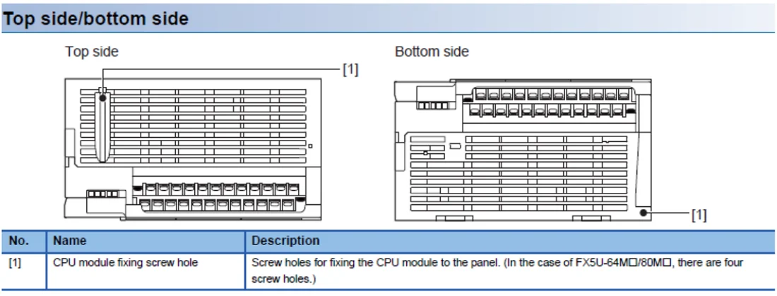
Mitsubishi Plc Fx5-16ex/es - Buy Mitsubishi Plc Fx5-16ex/es Product on Alibaba.com
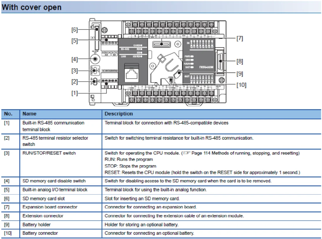
「乾貨」 三菱FX5U PLC模塊硬體接線圖匯總,收藏一下 - 每日頭條

