Vt Commodore Ignition Wiring Diagram, Complete Wiring Diagrams For Holden Commodore VT, VX, VY, VZ, VE, VF, 5.36 MB, 03:54, 32,796, John Amahle, 2018-08-01T19:37:41.000000Z, 19, Vt Commodore Ignition Wiring Diagram, to-ja-to-ty-to-my-to-nasz-swiat.blogspot.com, 1272 x 1800, jpeg, bcm pcm 12j swiat nasz, 20, vt-commodore-ignition-wiring-diagram, Anime Arts
2) connect one of the 2 same color wires to one side of the line and the other of the 2 same color wires to the other side of the line. 1) connect single color wire to common. 2) join 2 same color wires to hot. Single color 2 same color single color 2 same color 2 same color 2 same color heater band wiring
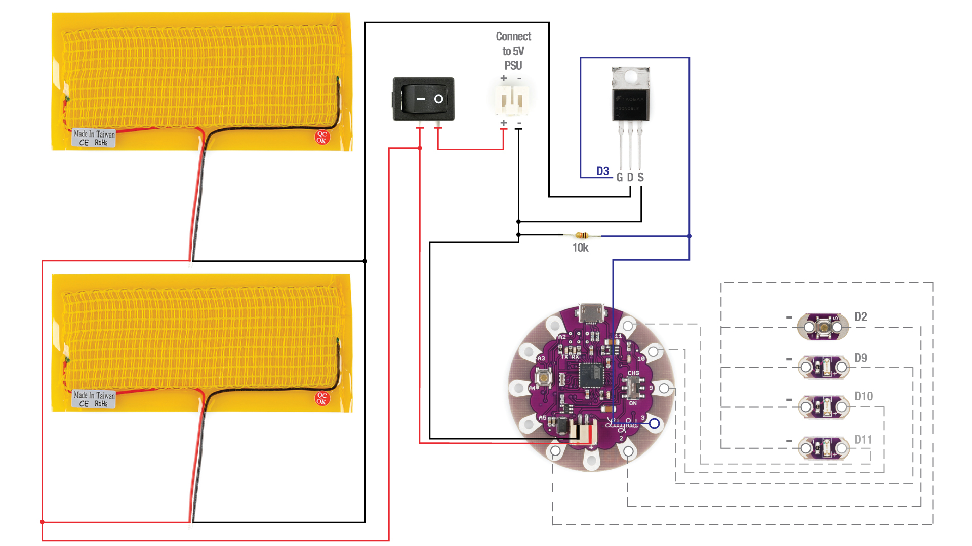
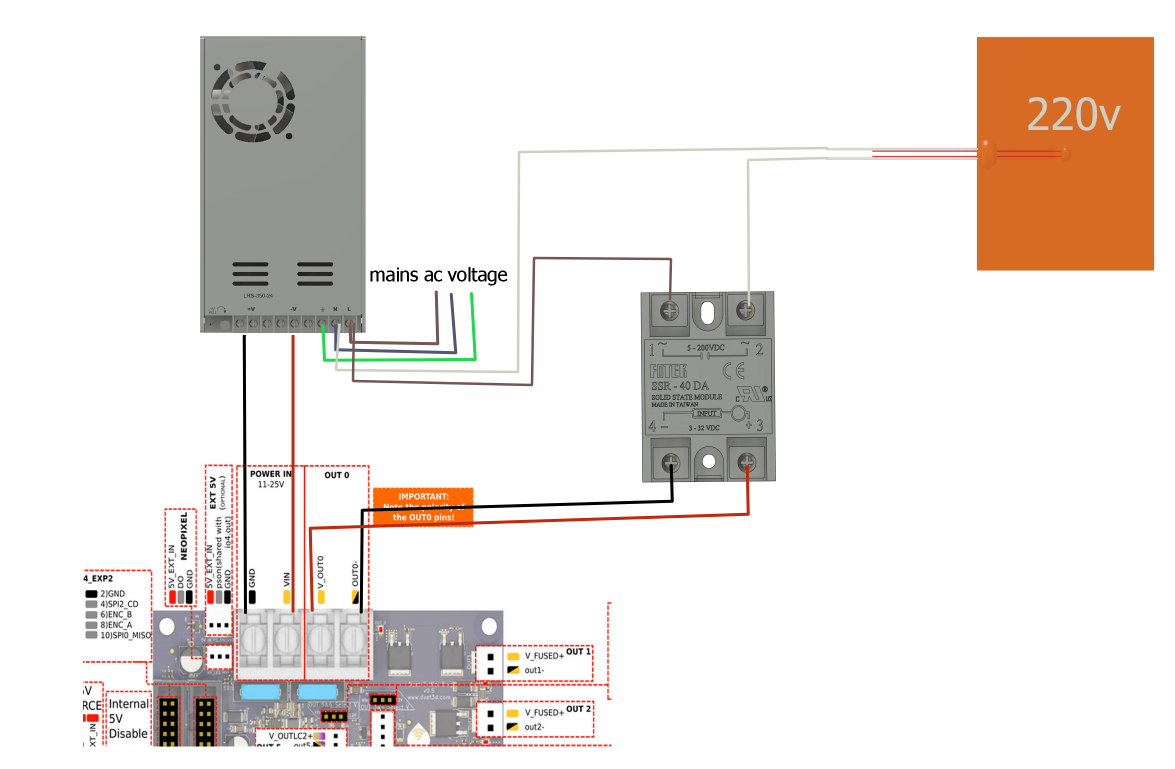
If it does make contact, the seat heater cannot be installed. See fig 3 8. Position the heating pad with the label facing down and the wire harness routed towards the back of the seat area. Adjust the pad so the thermostat is located approx. 2hspcp heater wiring diagram figure 4 2) the black (hot) lead and the white (neutral) lead on each spx heater are supplied with factory installed ring terminals. Connect ring terminals to designated terminal blocks as per wiring diagram. The green (ground) lead should be connected to the grounding bar as per wiring diagram. A heating pad is a small electrical device with a continuous electrical wire encased in a plastic pad. Heating pads include a removable fabric cover;
The heat pad and vibration - Robert Stenhouse DAT blog
Drawing Power for Heating Pad

The heat pad and vibration - Robert Stenhouse DAT blog
Electrical Wiring Diagram Heating Pad - Wiring Diagram & Schemas

Wiring Diagram Heating Pad - Wiring Diagram and Schematic
[DIAGRAM] Heating Pad Wiring Diagram FULL Version HD Quality Wiring Diagram - PVDIAGRAMSARAHI
![Heating Pad Wiring Diagram [DIAGRAM] Heating Pad Wiring Diagram FULL Version HD Quality Wiring Diagram - PVDIAGRAMSARAHI](https://blogger.googleusercontent.com/img/proxy/AVvXsEgWBh0G8tsl8VLBu3oSTcPLnQUmSxqRoFm9Bb6NIpATd3lduzUiz47aIYh7HVE4hgNFJCYg74BxX1LKF8fRNeExu-XyXx0i_n_fv6ETpjwpI5szMSM9g9McNVINA2GnnkTS7uS56dnPLKzdF4hfiE-mjsQYJSJY5e-QwJmfGcGQHAXf1i6o0h6is-l-kmkZqg3c25H6easff0Gitzm_Bmza0ErCNWRS5XSl6Ik4gItF=s0-d)
Patent US5432322 - Electric heating pad - Google Patents
Wiring Diagram Heating Pad - Search Best 4K Wallpapers

[DIAGRAM] Heating Pad Wiring Diagram FULL Version HD Quality Wiring Diagram - PVDIAGRAMSARAHI
![Heating Pad Wiring Diagram [DIAGRAM] Heating Pad Wiring Diagram FULL Version HD Quality Wiring Diagram - PVDIAGRAMSARAHI](https://www.tritekelectronics.com/images/stories/pdf_files/Philmore/lpad_wiring_stereo.jpg)
Heating pad wiring diagram. Wiring Diagram 174953. - Amazing Wiring Diagram Collection

